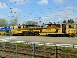
- Plasser & Theurer Unimat 08-475 4S-R, 24.10.2010 garat la linia 1 Gara Buftea
- Plasser & Theurer Unimat 08-475 4S-R, 24.10.2010 garat la linia 1 Gara Buftea
- Plasser & Theurer Unimat 08-475 4S-R, 24.10.2010 garat la linia 1 Gara Buftea
Increasingly higher speeds and transport outputs have altered the designs of switches and placed higher demands on the machine used for maintenance.
This requires conscientiousness and perfection in the construction and maintenance of high capacity lines.
In response to this challenge Plasser & Theurer has developed and built high capacity machines, which are already operating successfully on many railway lines around the world.
With the Unimat 08-275/4S an important, innovative step could be maid in switch maintenance for the treatment of modern, high-capacity switches and crossings. Heavier switch designs due to the use of concrete sleepers and heavy rail profiles can now be treated effectively and carefully with the help of the 3-rail lifting, the pivoting suspension of the tamping unit and the large bogie pivot spacing. Retaining these constructional features, the Unimat 08-475/4S represents a further step towards perfectioning switch maintenance.
The machine
The main frame of the machine is in one piece and rests on two 2-axled bogies. It is arched over the area of the work unit so that there is a full view onto the working area and sufficient space for free movement of the units.
The rear section of the machine is connected to the main frame by a pivot and rests on steering axles.
The solid design of the frame tasks into accounts the special requirements of the lifting and lining forces on heavy types of permanent way. The extended distance between bogie pivots also ensure a gentle bending lines and thus minimizes the lifting and lining forces needed.
The machine has three cabins and the front cabin houses all operating controls for transfer travel as well as driving and operating controls for the leveling and lining measuring unit. The ALC - automatic guiding computer – installed here enables control of the leveling and lining operations when the target track geometry data is known or, if the target track geometry is not known, measurement of the actual track geometry with subsequent calculation and optimization of the target geometry.
The work cabin directly in front of the work units is spaciously laid-out so that the operator has an excellent view onto the tamping units, the combined lifting and lining unit and the synchronous 3-rail lifting unit
The work units are operated from the two seats positioned in the cabin. It is also possible, by a simple switchover, to control all operating functions for work from one seat.
The cabin at the end of the machine provides monitoring and operating controls during transfer travel and for the sweeper unit (optional).
The machine is completely roofed over from the front cabin to the rear cabin. A gangway connects the front cabin and the work cabin. In the area between the work units there is a catwalk for assembly and serving work, which can be reached from the rear cabin. This means that along its entire length the machine is accessible from inside.
Tamping units
The four tamping units with double tilting tines are the essential feature of this machine. The outer units are mounted on telescope jibs and can be slewed out far enough that the deflecting line of the switch can also be tamped. The inner tamping units are positioned to be displaceable on vertical guide columns so that they can be applied in the area inside and outside the rails. Both the inner and the outer units can be pivoted individually to adapt to the slanting position of the sleepers.
The left-hand tamping unit illustrates the maximum displacement of the outer tamping units. The lateral range of the tamping tines is 3 200 mm from center of track. This design enables the long sleepers to be fixed in place in one pass.
In their basic position the 16 side-tilting tamping tines have the same positioning as on plain line tamping machines. This guarantees optimum maintenance of tracks as well as maintenance of the entire switch area.
Combined track and switch lifting and lining unit
This unit is proven design is positioned directly in front of the tamping units. It can be displaced by ±200 mm lengthwise along the rails. On tracks roller-lifting clamps performs the lifting. On switches the lifting hook is used which grips either underneath the rail head or rail base. During forward motion the unit adapts to the rail curvature without transmitting forces to the rail.
Synchronous 3-rail lifting
Switches and crossings are complex, heavy-duty permanent way components of high precision. No undue tensions should be transmitted to the switch in the course of maintenance. For this reason the machine is equipped with an additional lifting device for the deflecting rail.
Depending upon the design of the switch and the working direction of the machine, a telescopic alarm is slewed out to the left or the right up max. 3 300 mm from center of track. The telescopic arm carries a double-flanged guide roller and a shank for the clamp. The latter is closed automatically during working operation. The 3-rail lifting is controlled from the operator’s seat in the work cabin. The leveling unit controls the lifting operating.
The outstanding features at a glance
* 4-rail tamping in addition to 3-rail lifting.
* Four tamping units working independently.
* Telescopic jibs to extend the outer tamping units.
* Tamping units can be adjusted to slanting sleepers from the operator’s seat.
With all its advantages, the new Unimat 4S sets the standard for perfect maintenance of switches and crossings
Technical Data
Length over buffers: 35 290 mm
Width: 3 000 mm
Height over top of rail: 3 700 mm
Distance between bogie pivots: 14 000 mm
Wheelbase of the bogies: 1 800 mm
Distance to bogie pivots rear axle: 6 700 mm
Wheel diameter: 920 mm
Total mass of the machine: 103 t
Axle loads front bogie : 17 t each
Axle loads rear bogie 20.75 t each
Axle load rear axle approx. 10 t
Drive: water-cooled diesel engine 370 kW (503 HP)
Four tamping units each with four tilting Inwards 15°
tamping tines, tilting angle of tamping tines Outwards 85°
Turning of tamping unit for slanting sleepers: up to ± 8.5°
Additional lift jib/arm
(distance from center of machine): 3 300 mm
Traveling speed under own power : 90 km/h
Drawing
- Plasser & Theurer Unimat 08-475 4S-R Drawing
http://www.plasserindia.com/en/machines ... 475-4s.htm