Tehnical Characteristics
Constructive and functional characteristics
- axle formula: Co-Co
- lenght over buffers: 19800 mm
- width: 3000 mm
- pantograph operating range under the contact line measured from the upper side of the head of rail: 4850 -+ 6700 mm
- distance between the centers of the bogies: 10300 mm
- distance between the extreme axles of a bogie: 4350 mm
- whell diameter in new state: 1250 mm
- whell diameter in semi-used state: 1210 mm
- total load:
a) with ballast: 126t + - 2% for 120 km/h version
b) without ballast: 120t + - 2% for 160 km/h and 200 km/h version
- axle load:
a) with ballast; 21t + - 2% for 120 km/h version
b) without ballast 20t + - 2% for 160 km/h and 200 km/h version
- nominal power: 5100 kW - continous
(powers up to max 6600 KW can be generated correponding to the short period services of the traction motors).
- traction force at the hoop in nominal service with semi-used ferrules
a) maximum speed 120 km/h version (gearbox ratio 1:3,65)
1) 100 % excitation at 69,5 km/h: 26500 N
2) 50% excitation at 90,5 km/h: 206000 N
b) maximum speed 160 km/h version (gearbox ration 1:2, 66)
1) 100% excitation at 92,5 km/h: 199000 N
2) 50% excitation at 120 km/h: 154000 N
c) maximum speed 200 km/h version (gearbox ration 1:2,108)
1) 100% excitation at 122 km/h: 150000 N
2) 50% excitation at 163 km/h: 110000 N
- starting traction force (gearbox ratio 1:3,65) : 440000 N for GL = 126 t
- starting traction force (gearbox ratio 1:2,66) : 288000 N for GL = 120 t
- starting traction force (gearbox ratio 1:2,108): 288000 N for GL = 120 t
- nominal power of traction transformer : 5790 kVA (continous)
Mecanic part
Bogies
The bogies and ther coupling are similar to those used for LE 5100 kW from the existing stock and they are in accordance with tehnical specification of DTB 3653 for LE with a maximum speed of 120 km/h and 160 km/h, respectively with a tehnical specification F.P./s BL 7061 for LE with maximum speed of the 200 km/h. They are equipped with mono block wheels and with a nominal diameter of 170 mm.
Locomotive car-body
The locomotive car-body is a metalic welded construction, self suporting, that bears the efforts due to the weight of the aggregates, the traction forces, colision and braking abd in homologated in acordance with ST 037/2008, approved by AFER. The locomotive car-body is desingned to provide the necesary space for fiting the equipment and the servicing, maintenance and driving the locomotive by the operating staff.
Electric part

The electric equipment is manufactured by Softronic and consist of the modernizations homologate in acordance with ST 26/2005, aproved by the AFER, namely:
- replacement of the voltage adjusment on the high voltage part, using the voltage switch and graduator, with voltage adjusment on the low voltage part using traction electronic converters CET-I-LE and CET-E-LE instead of rectifiers from the circuits of traction motor spply;
- modification of the driving board;
- replacement of the classic controller with handle-type controller;
- introduction of the supply system for the auxliary services with static converters of variable voltage and frequency;
- mouting of the measurement and speed registration;
- saftey and vigilance type IVMS with integrated INDUSI and DSV;
- mouthing of the locomotive control instalation type ICOL;
- introduction of the consumed electric energy metering;
- heating of the driving cabins with self protected forced convection air- heating;
- mouting of the air-conditioning in the drive cabins;
- the mouting of the axles temperature measuring instalation IMTO type and constructive preparing for the optional mouting of the equipments associeted ERTMS.
The electric part of the locmotive is composed of the loe and high voltage apparatus, the main transformer, one electronic traction converter foe each traction motor, controlled rectifer for excitation, static converts for the auxliary services ( for the screw motor compresor, motoventilators, oil pump), traction motors, control equipment and auxliary services, equipment with microprocessors for control, diagnostic, protection and signaling, specific electric circuits and other accesories.
High voltage equipment
The high voltage equipment is desingned to operate at 25 Kv nominal voltage and it is acording to HEC 60077. It is mainly placed on the roof of the locomotive and in the high voltage compartment of the machine room and comprises:
- pantograph - 2 pieces, for curent capturing;
[img]http://www.railnet.ro/download/file.php?id=4305&sid=530c30010ae53d879e4f4197ac92fd14[img]
- overvoltage lightning arrester;
- disconnextiing switches;
- high voltage measuring transformer (optional);
- vacuum circuit breakers;
- support isolators and bushings.
The tehnical characteristics of the high voltage apparatus are enclosed in the manufacturing documents.
Main transformer unit and the flattening self
This equipment is acording to SR EN 60310:2004
The main transformer unit caries out the function of reducing the supply voltage of the circuits for traction motor, splpy the auxiliary services and the train heating, being placed in the machine room.
The voltage adjusment on the traction motor is made with the contrlled rectifers.
The main transformer unit is single phase type, construction in oil with forced circulatio of the oil through a pump, the oil circulates through a cooler ventilated with motoventilators.
The transformer encloses three transformer units assembled in the same tank, as follows:
- transformer for train heating and auxiliary services;
- traction transformer;
- transformer for the excitation of the traction motors in traction conditions and electric braking.
Constructive elements :
- magnetic circuits: made of cold-rolled laminated siliceous sheets;
- winding and conections: made of copper conductor isolated with electro insulathing paper;
- tank and cover made of welded steel sheets;
- cooling battery;
Main characteristics of the main transformer:
Maximum temperature of the cooling air: + 40*C;
Nominal frequency: 50 Hz
In the locomotive, the area of the terminal connection is secured agaist touching, the acces being allowed only when the transformer is disconected from the network and earthed throught the earthing device.
The flattening self is the element with relative big inductance, series connected in the armature circuit of traction motors in order to reduce the current undulation throught MT.
The flattening self is a monoblock type with six galvanic separate circuits, one for each traction motors.
Electronic traction converters
They are manufactored according to SR EN 61287-1:2007.
Electronic traction converters for traction motor armature (CET - I - LE)
The electronic converter for the traction motor armature (CET-I-LE) is a element of the power circuit, placed between the transformer and each of the traction motors. It is intendet to supply the motor armature in traction conditions from each secondary winding of traction transformer and to enable the current circulation beteewn the armature and braking resistance in electric rheostatic braking conditions.
As construction, the converters for the armature are bloks, one for each traction motor, in a specific structure, with fans that cool the rectifier and the traction motor.
The constructive forn, the dimensoins and all the tehnical conditions are regulated by the tehnical conditions are regulated by the tehnical documentation and the product standard of the convecter for the traction motor.
The assembly of these converters is made in blocks S1 ..... S6 .
The tehnical characteristics of the converters for armature are :
- nominal supply voltage: 943 Vac
- maximum supply voltage: 1068 Vac
- nominal current: 1250 Adc
Converter for the excitation of the traction motors (CET - E - LE)
The converter for traction motor (CET - E - LE) is manufactored according to SR EN 61287 - 1:2007 and is intended to suply the series connected traction motors excitations both in traction and braking conditions from the braking transformer secondary winding. Constructively, the converter for excitations is a block, with integrated cooling system, the cooling air being taken in from the machine room and taken out the exterior thriugh cut-outs made on the locomotive fllor.
The constructive form. the dimensions and the tehnical conditions are regulated throught tehnical documents and the product standard of the excitations converter. It is mounted near the main transformer.
Technical characteristic:
- nominal input voltage: 111 Vac;
- input voltage frequency: 50 Hz;
- output rated current: + / - 1060 Adc;
- control voltage: 110 Vcc .
Traction motor
The locomotive is equipped with six traction motors type LJE 108-1, manufactured according to SR CEI 60349:1999, UIC and SR EN 61377-2:2003 .
The motor is hung up type and actuates the cylindric wheels drive through a torsion shaft actuated by the rotor hub.
Constructive elements:
- The motor casing consist of a external steel cover (welded construction);
- The rotor consists of a hub on which the magnetic core with rotor winding and the commutator are pressed;
- Windings: rotor (simple loop, in two layers) for excitation;
- Bearings brackets (with cilindrical rolls) which support the rotor.
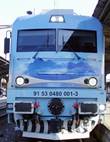
- 40-2004-6 on Chitila station, may 2011 / Foto: Daniel
Tehnical characteristics:
- continuos conditions: 850 kW, 770 V, 1180 A, 1100 rpm;
- one-hour conditions : 900 kW, 770 V, 1250 V, 1085 rpm;
- maximum current : 2000 A
- maximum rotation : 1930 rpm
- isolation class : F
As construction, the traction motors are desingned to be mounted completely hung up on the bogie and individual driving of each axle throught a jagged coupler and traction gear.
The constructive form, the dimmensions and all tehnicall documentation and the product standard of the traction motor.
Auxiliary services
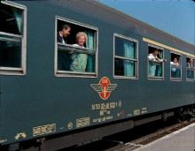
- The same machine with a Fast Train hedding to Brasov / Foto: Daniel
The auxiliary services of the locomotive are ensured mainly by three-phase electrical motors ( 3x380 V, 50 Hz), manufactored according to SR CEI 60349:1999 and UIC 619, for driving the compressor, fans for rectifiers and traction motors, transformer and braking resistances, the oil pump of the main transformer, as for the electrical mono-phase motors for ventilation of the machine room, control and protection blocks, supply of the heaters from the driving cabins, central light, etc.
The auxiliary services are supplied for winding for auxiliary services and heating through voltage plugs (0;360 V; 460 V; 1507 V). the block with five static converters that provides a three-phase system of symmetric voltages for supplying the thre phase motors is conected at plug 0 - 386 V.
The spply method for the auxiliary services motors is shown in the auxiliary services diagram.
The tehnical conditions of manufacturing, testing and reception are regulated throught the tehnical documentation and tehnical specification of the static converters or of blocks with static converters for supplying the auxiliary services.
The folowing equipment are also connected to the auxiliary services:
- Auxiliary transformer;
- Loading station for storage battery;
- The storage battery;
- Auxiliary asyncronous motor compresor and the static converter associeted with it.
De pus desen pagina 7
[b]Electronic equipment for control and adjusment
- Foto: Daniel
The electronic equipment for control and adjusment ensure the execution of all necessary controls for the locomotive operation in traction and electro dynamic braking conditions and it is manufactured acoordind IEC 60571:1998 .
The electronic equipment can operate in the range of outside temperature from - 25*C to +70*C and geberally ensures the folowing funtions:
- control of electronic traction converts armature and the traction motors excitation;
- control of auxiliary services;
- limitation of traction and braking currents;
- equipment protection at switching from traction to braking and inversely;
- protection at over - passing of the traction current, over voltages, minimum voltage in the catenaries hanger, maximum braking current.
- effective protection at slipping and blocking;
- blocking the control circuits when the controller is on "bloked" position etc.
Constructively, the electronic order equipment consists of the control installation of the locomotive (ICOL), is an electronic rack, mounted in S7 block. This electronic unit carries out the working conditions in the traction and braking, other necessary controls and coordinates all the serial connections with other programmable units and the two cabin displays, one for each board;
This installation controls the pantograph and the circuit breaker, monitors and signals the locomotive protections, the main equipment state and displays all the necessary information .
It ensures the control of the static converter for actuanting the screw compressor motor, the five static converters for the redundant driving of the auxiliary services, ensuring their protection and diagnosis.
ICOL installation also ensures the protections on currents of the traction motors, slipping, overcharge, overvoltage and earthing.
Control equipment
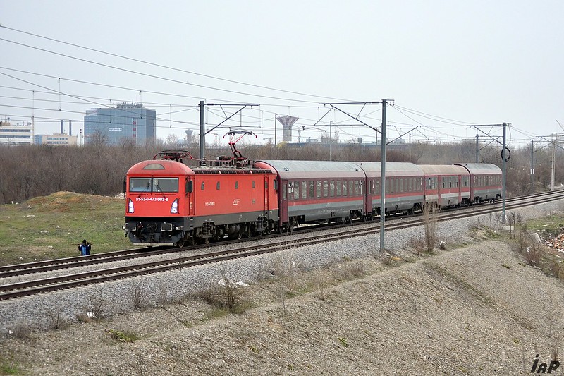
- The same machine with an IC train / Foto: Daniel
The control equipment manfactured acording to IEC 60077/1999 consist of buttons, commutators, relays, electroventiles, plugs and male connectors with multiple contacts, etc. These are enclosed in the 110 V d.c control circuits; the control voltage is supplied by the storage battery connected in buffer with the station for battery charging.
The tehnical and constructive data concering the control equipment are regulated through the tehnical documentation of the locomotive.
Protection and signaling equipment
The protection and signaling equipment is acording to IEC 60077/1999 and cotains:
- single-pole automatic cut out and thre pole cut-out for protection of the circuits and electric machines;
- thermal or intermediary relays for protecting the auxiliary services;
- maximal curent relays;
- pressure relays;
- electronic devices;
- acoustinc signaling, optical signaling, board display, etc.
These devices operate directly through ICOL over the circuit breaker and/or over the control and adjusment system of the locomotive.
The locomotive protections of the power circuits are caried out the level of converters for the armatures and excitations of traction motors: protection on slipping, protection on over charge, maxium average current, short circuit throught the traction motors, protection at maxium voltage on the traction motors, protection agaist the breakdowns of the traction pinions, grounding protection.
The protections on the auxiliary services are carried out to the level of static converters and ICOL instalation: protection for overcharge, short circuit, over temperature, maximum voltage.
The security system of the locomotive running on the rail concering the condition of the driver and the influence of rail singns is ensured through a compact instalation that covers the punctual speed control, the system of surveillance and vigilance , measuring instalation and speed inidication and recording, but also through the radio - telephone instalation for fast communication of the driver with traffic dispatcher.
Electronic control and adjusment equipment ensure the signaling of the input, state, output values and faults, memorizing the state of important measures and fault appeared for a determined period of time.\
On the board display there are indicated the last faults and their description, on demand.
The list of all input, output values, protections, signaling, codes and faults descriptions, functions, etc. is presented in the manufacturing documentation and in the maintenance and operation intructions.
The traction characteristic of the locomotive are presented in Addendum 2.
The traction characteristic of the locomotive are presented in Addendum 3.
Lighting
The tehnical data concerning the lighting equipment of the locomotive are regulated by UIC 651/2002-OR and the tehnical documentation of thhe locomotive.
The locomotive lighting is ensured throught electrical light units supplied with adequate voltage as follows:
- general lighting of the locomotive: 100 V a.c with the possibility of automatic commutation on 110 V d.c voltage from the storage battery. The bulbs foe each unit are of 25 W;
- the central lights are supplied at 30 V a.c and have a power of aproximately 160 W.
Train heating
For heating the train, the locomotive ensures the supply source of the electrical heaters from the pasangers cars in accordance with UIC 552. This source is the secondary winding of 1500 V of the main transformer, having a power of 700 KVA.
The command concerning the closing of the train heating supply circuit is given by a control key, the circuit ensures the protection of the staff coupling the passenger cars to the 1500 V, 50 Hz supply columns of the locomotive.
Coupling of heating circuit with the passengers cars is made through the cables with double cards and special plugs that are located two by at each of the locomotive ends.
Air-conditioning of the control cabins
For creating a enjoyable climate in the control cabin in accordance with the UIC 651 requirements, the followings are provided:
- frontal windows with integrated electrical resistance for thaw;
- heating plate foar each control board;
- 2 forced convection air heating of 2 kW each, with ajustable power, fail safe (resistant type PTC);
- an air-conditioning installation installed on the cabin roof for maintaining a constant, enjoyable temperature, during summer (optional)
- lateral heating radiator for the driver and optional for the driver's assintant.
Return current circuit
The return of the current from the transformer primary circuit to the traction substation is ensured throught the absortion transformer and the contacts, avoid the passage of the current throught the bearings of the axle bousing.
Grounding device
The grounding device ensures the staff protection by grounding of the primary main winding of the primary transformer. The device has a mechanic interlock with a key that can be taken out only in position "grounded", situation when the circuit-breaker conection is blocked.
Electric brake
The locomotive is equipped with a rheostatic brake. The motots act as generators with separate excitation on resitance of 0.42 Ω, 960 A. The braking resistance are grouped in two blocks (S9 and S10) with a forced ventilation.
Adjusting the braking force is made by hand, according with the braking current prescribed, throught the adjusment of the excitation current common to the six windings of excitation series connected supplied by the excitation converter.
The rotor braking current, as well the excitation one are limited to maximal values, not dangerous, by ICOL and the converters for the armatures and the excitations of the traction motors. The braking characteristics is given Addendum 3
Pneumatic part
Instalation for compresed air and pneumatic brake
The compresed-air instalation of the locomotive and pneumatic brake consist of a screw electro compresor type ECE 3,5 LE, compresed-air tank and pneumatic equipment.
The electro-compressor delivers compresed air, carrying out of maxium presure of 10 bars; the starting process of the compressor and maintaining the presure in the necesary limitis for eficient operation is automated.
For the initial pantograph lifting and the operation of the main switch, the locomotive is equipped with an auxiliary electro-compressor, supplied from the storage battery, through a static converter.
Compressed-air brake (pneumatic)
The locomotive is equipped with an automatic pneumatic brake type KNORR K-GPR with an air distribuitor type KE 1c - SL that ensure disengagements in stages and with direct paneumatic brake type OERLIKON with a prresure relay KR1 for shortening the braking times.
The pneumatic brake of the lomotive consists of:
- automatic brake type Knnor K-GPR with the mecanic tap FHD4-EP mounted on the board in each control post, with an air distributor type KE 1c -SL that has the role to perform a moderate braking - disengagement (in steps). The pressure tranducer is of type Du 15. The automatic braking is independent from the direct brake with air and opertes on the locomotive and the wagons of the towed train.
The Knnor components used are authorized elements of the HDP-EP system, that permits this system to be implemented as optional when the brake type of the cars permits the use of the electro-pneumatic brake. An ALE 10 device supplied with 110 V d.c. voltage is provided for brake releasing.
- direct pneumatic brake type FD1 - Overlikon operated through the manoeuvre tap for the direct brake mounted in each post at the right side of the mechanic can vary the pressure in the brake cylinders from 0 to 2,1 bars. The direct brake is used as manoeuvre brake recommended for speeds between 0km/h and 40km/h or wehn the locomotive runs isolated. For shoterning the braking times (uder 10 sec.) pressure relays KR1 can be introduced in the circuit of the direct brake.
Necesary air for the brake installation
The necesary air for the braking installation is produced by a screw electro-compresosor type ECE 3,5 LE, driven by a 37 kW asyncronous electric motor wich provides the flow and the 10 bars pressure necessary for the installation.
The installation is provided with adequate devices for air separation and filtration. The air filtration on the aspiration part is made through a filter with oil bath. The compressed-air installation is provided with a cooler, cyclone separator, motoventilator and drying thanks with silicagel and automatic purging of the water condensation and the impurities controlled by ICOL.
The filtration and drying of the operating air is provided in the supplying circuit of the main switch. The air is stored in two main thaks of 500 l each.
The compressed air installation also contains auxiliary thanks, for temporization, equalization, regenaration and reserve.
The pressure caried out in the pneumatic installation are:
- in the feeding pipe: 10 bars;
- in the general pipe: 5 ± 0,1 bar;
- in the direct brake circuit: 2,1 ± 0,2 bar;
- in the electro pneumatic apparatus circuits: 5 bars.
Pressures in the brake cylinders:
- for low power braking (G and P): 2,1 ± 0,2 bar for Vmax =120 km/h, 2,35 ± 0,2 bars for Vmax 160 km/h and 2,8 ± 0,2 bar for Vmax 200 km/h;
- for high power braking (R) for V < 70 km/h increasing or V < 60 km/h decreasing: 2,1 ± 0,2 bar for LE with V max=120 km/h and 4,8 ± 0,2 bar for Vmax = 160 km/h and 5,4 ± 0,2 bar for V max = 200 km/h;
- for high power braking (R) for V > 70 km/h increasing or V > 60 km/h decreasing: 4 ± 0,2 bar LE with V max = 120 km/h and 4,8 ± 0,2 bar for V max = 160 km/h and 5,4 ± 0,2 bar for V max = 200 km/h;
- for direct braking: 2,1 ± 0,2 bar;
The brake is operated by one cylinder for each axle for LE with V max = 120 km/h and 160 km/h and by 4 cylinders for each axle for LE with V max = 200 km/h. At this last version, at axles 3 and 4, two of these cylinders, located towars triangles, are designed to the spring brake for pinning (unilateral actions).
Force at the piston rod:
- P=42,564±1,631 kN for braking system R
- P=21,363±1,631 kN for braking system G-P
The multiplication ratio: rod gear/block/cylinder is of 1:8,48
The braking distance during isolated run on the railway at V=100km/h is Sf=600 m.
The alarm brake can be operated from each board throught an alarm tap.
For saftey installation type INDUSI, a separate air circuit that can activate the emergency brake, in case of command, is provided.
The sander are equipped with elecroventiles, whose action is associated with direction of movement, being supplied with a pressure of 10 bars.
A separate circuit 10 bars is provided for the wheel flange lubrication installation, with the possibility to isolate the air on the supply part.
Other details about the pneumatic installation are enclosed in the manufacturing documentation.
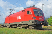
- A closer look of the engine / Foto: Daniel