Tehnical Caracteristics
This new romanian electric engine is assigned to Class 48 - the newest engine class in Romania.
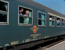
- The new Trans Montana electric engine from Softronic / Photo: Daniel
Constructive and functional characteristics
- axle formula : CoCo
- length over buffers: 19740 mm
- windth: 3000 mm
- pantograpf operating range under the conctact line measured from the upper side of the head of rail : 4850 - 6700 mm
- distance between the centeres of the bogies: 10300 mm
- distance between the extreme axles of a bogie: 4350 mm
- wheel diameter in new state: 1250 mm
- wheel diameter in senu-used state: 1210 mm
- total load without balast: 120 +-2%
- axle load: 20+-2% f
- nominal power: 6000 kW
- traction force at the hoop in nominal service with semi-used ferrules: 292 kN
- nominal power of traction transformer: 5790 k V A
- 91 53 0480 001-3 / Photo: Daniel
- Detaliu pantograf tip Schunk - the Schunk type of pantograph / Photo: Daniel
- Detaliu roata - wheel detail / Photo: Daniel
- Locomotiva Trans Montana in Gara de Nord - Trans Montana in Gara de Nord Station, Bucharest / Photo: Daniel
Characteristics of the railway where the lcomotive can normally function
- rail gauge: 1435 mm
- curves minum radius in depots: 90 m
- the locomotive must run totally safe in curves with a radius of 170 m, slope of 26%, over raising of 115 mm, over widening of 25 mm, at speed of 60 km/h;
- maximum lateral displacement of the conctact wire in alignment with the railway axis: +- 400 mm
- Contact line rated voltage / rated frenquency 25 kV/50Hz
- maximum voltage: 27,5 kV
- minimum voltage: 19 kV
- short term minimum voltage: 17,5 kV
- short term maximum voltage: 29 kV
Mechanical part
Bogies
The bogies and their part couplers are similar to those used for LE 5100 kW from the existing stok and they are in accordance with tehnical specification SBL 7081 for LE with a maximum speed of and 160 km/h, being equiepped with mono-block wheels and axles with 170 mm nominal diameter.
The bogies consist in a new gear, with a report close to the 120 km/h version, but with a maximum speed of 160 km/h, possible by using the asincronous traction motor.
The secondary suspensions is made with Hurglass elements.
The boghies frames are made by SOFTRONIC and the axles are mounted by CAROMET.
- Detaliu cutie de osie si lampa de pozitie - detailed axle box and lightings / Photo: Daniel
- Detaliu cutie de nisip si inductor de cale si prindere a osiei in cadrul boghiului - Details with the sandbox, rail inductor and fixed axle on the bogey / Photo: Daniel
- Detaliu suspensii - detailed suspension system / Photo: Daniel
- Ansamblu suspensie, balancier tractiune si tiranti - Groupage of suspension, traction beamer and thrust / Photo: Daniel
- Cutiile acumulatorilor - battery's boxes / Photo: Daniel
- Boghiul - the bogey / Photo: Daniel
Locomotive car body
The locomotive car body is a steel whelded construction, self suporting, that bears the efforts due to the weight of the aggregates, the traction forcces, collision and breaking and it is homologated in accordance with ST 037/2008 approved by AFER. The locomotive car-body is desingned to provide the necessary space for fiting the equipment and the servicing, maintenance and driving the locomotive by operating staff.
The locomotive car body is equipped with crash absorbent buffers and an improved snow plow.
The rear view mirrors are replaced with rear-cameras and an associated recordind system, which can also record the sound in the driving cabin.
The machine room is pressurized with filtered air and the air conditioning in the cabin has refresing system according to UIC 651.
- Postul 2 al locomotivei - engine's 2-nd driving post / Photo: Daniel
- Detaliu plug de zapada imbunatatit - the new improved snow plough on detail / Photo: Daniel
- Detaliu far lateral - side light on detail / Photo: Daniel
- Detaliu de lumina de pozitie frontala - front light position detail / Photo: Daniel
- Detaliu aparat de legare - the coupling gear on detail / Photo: Daniel
- Ferestrele frontale ale cabinei - the front windows of the cabin / Photo: Daniel
- Inscriptie din postul 2 - label from cab nr.2 / Photo: Daniel
- Cabina masinii - engine's cab / Photo: Daniel
- Bordul masinii - engine's board / Photo: Daniel
Electrical part
The electric equipment are manufactored by SOFTRONIC and they have as the main modernized element the converter CET-A type whichperform the simultaneous adjusment of the asynchronous traction motor frequency and voltage, by using vector control. There are also used other upgraded equipment which have proved their reliability in aplications such as: stick, auxiliary sevices supply sistem with static converters for variable voltage and frequency ICSA type, speed recording and measurement instalation, saftey and vigilance ICO type, introducing the consumed energy counter CEL typr, air conditioning instalation for the driving cabins and also the axle temperature measurement instalation IMTO type and the cameras instead of the rear view mirros.
The electric part of the electric locomotive is consists of the high an low voltage apparatus, main transformer, one electronic traction converter for each traction motor, static converter foe auxiliary services ( for the serew compressor moto, fans, oil pump, wather pump), traction motors, apparatus for comand and auxiliary services, equipment with microprocessor for control, diagnosis, proctection and singnaling, specific alectric circuits and other accessories.
- Manete franare electro dinamica - Electro dynamical braking toggle / Photo: Daniel
- Sistem INDUSI si regim de franare- INDUSI system and braking regime / Photo: Daniel
- Vitezometru Softornic - Softronic speedometer / Photo: Daniel
High voltage equipment
The high voltage equiement is designed to operate at de 25 kV nominal voltage and it is manufactured according to IEC 60077. It is mainy mounted on the roff of the locomotive and in the high voltage voltage compatment of the machines room and comprises:
- advanced pantograf - 2 pieces, for the curent collenting (with brush cranking detection and rapid descent);
- overvoltage surge arrester;
- disconneting switches;
- high voltage measuring transformer;
- vacuum circuit breakers;
- supportinsalators and bushings.
- Trans Montana Softronic / Photo: Daniel
Main transformers unit
This equipment is manfactured acordind to SR EN 60310:2004 and ST 047/2010 requirements.
Manufactured acordind to SOFTRONIC' s original project, the equipment suplies the traction converters though six secondary, the auxiliary services and the train heating circuit.
The main transformer unit, mounted in the machine room, caries out the function of reducing the supply voltage of the traction motors circuits, auxiliary services and the train heating.
The main transformers unit is single-phase type, construction in oil with forced oil corculation though pump, the oil being driven by a ventiled cooler by means of motor ventilators.
The transformer secondary windings are as follows:
- traction windings: 6x1237 kVA - 25/6x1,050 kV;
- windings for train heating: 700 kVA - 25/0,394 kV;
Constructive elements:
- magnetic circuits: made of siliceous steel cold laminated.
- widings an conections; made of cooper conductor insulated with electro-insulating paper.
- tank and cover; made of welded steel.
- cooling battery.
Main characteristics of the main transformer:
Power (KVA) Voltage (V) Current (A)
Primary winding: 8322 25000 333
Traction wimding: 7422 6x1050 6x1178
Winding for auxiliary services: 2000 394 508
Winding for traian heating: 700 1500 467
Maximum temperature of the cooling air: +40'C
Nominal frequency: 50 Hz
Electronic traction converters for asynchronous tractioous motors (CET - A)
They are manufactored according to SR EN 61287-1:2007.
They are modular and independent, one for each traction motor, mechanical compatible with the S1 .... S6 blocks for the classic 5100 kW locomotive.
The cooling is made with wather and glycool by means of traction motor ventilators.
The converter operates in traction conditions, regenerative braking of rheostatic braking at unity power factor accordind to SREN 50388 .
Robustnessand simplycity of desing, manufactoring low price, high reliabity with good electromechanical performance of the asynchronous motor makess it the most efficient electric drivingmachine. The only disadvantage it used to have: speed adjustment dificult and les efficient throught classical methods ( rheostatic adjusment or adjusment by voltage varation), is now eliminated by using the method of vector adjusment throught electronic converter.
The electronic traction converter is an a.c. single-phase / a.c. three-phase converter. These converters containan input conctactor and a pre-loading circuit, a four-quadrant rectifer with high power factor 4QC, an intermedary voltage circuit, a chopper for rhoestatic brake and thre -phase inverter.
The 4QC rectifer, made of four IGBT, can fuction in four-quandrant allowing the locomotive to be used in regenative braking conditions, The intermedary voltage circuit contains capacitors an a filter for the second harmonic. The chopper for the rheostatic braking is made of IGBT and a diode and introduces the braking resistance in the intermediary circuit of the locomotive for the rheostatic braking. The three-phase inverter, made of six IGBTs, transforms the continuous voltage from the intermedary circuit in three-phase alternative voltage for the asynchronous motor supply in traction conditions or it transforms the three-phase voltage produced by the motor in continuous voltage in case of braking conditions.
The spply of the asynchronous motor by the traction electronic converter enables the starting and the adjustment of the motor speed by the fied orientation method. The speed varation is diret proportional with the supply voltage frequency varation, on the entire adjustment range. Until reaching the nominal voltage, the adjustment is made in conditions of maintaining the U/f = constant, the speed adjustment being done in constant magnetic field flu. For high speed, the voltage is maintained constant and the frequency varations require varations inversey proportional with the magnetic field flux.
The electronic traction converters are replacing the S1 .... S6 blocks from the classic locomotive having the same mounting dimensions and same gauge.
By using the asynchronous traction motors supplied from the independent converters, the traction and electric braking performances are improved and the amintenance costs are reduced. As an extra benefit, pssibility appears for regenerative breaking with financial consequences that enable a faster investment pay off.
Constructively, the electronic traction converters are desingned as blocks, one for each traction motor. with vemtilators that cool both the converter and the traction motor. The power electronic modules are cooled by water-air system made of a water-air radiator, a water pump and aluminum water cooled radiators. The cooling liquid is a mixture watee-glycol which allows the usage of the converters in negative temperature conditions.
The tehnical characteristic of the converter are:
- rated supply voltage: 1050 V a.c.
- rated output voltage: 1200 V a.c.
- output voltage frequency: 0 .... 125 Hz
- rated output current: 650 A a.c.
The locomotive is equipped with six traction motor type MTA-ES-1008, manufactored according to SR CEI 60349:1999, UIC 619 and SR EN 61377-2:2003
The motor is hung up type and operates the spur-gear drive trhough a torsion shaft driven by the rotor hub, identically with the continus current traction motor LJE 108-1 type used in previousapplications.
The motor corresponds to the conditions prescribe by the ST-035 specification that are according with SR EN 60349-2.
The traction motor is manufactored accordingly to the new SOFTRONIC desing and it is compatible with the LJE 108 motor from mechanical poibt of view, but with increases power and higher maximum speed.
The constructive shape is of special type, for IP 12S protection degree.
The motor is cooled by forced ventilation with motor ventilators group AMV1-2 wich ensure a flow of 1,8m3/sec.
The rolling bearings are made as follows:
- at the coupling part wtih the cogged cuopling (traction part) - bearing un-insulated in elctrical terms NU1036MC3;
- at the part opposite to traction - bearing insulated in electrical terms NUP230MC3.
The motor is equipped with three thermo-resistances Pt 100 ohm at 0C type for supervising the heating of stator windings. The motoe is equipped with inductive proximity sensor magnetically cuopled on radial direction with a cogged ring placed on the cover that closes the cougged coupling betwen the motr and torsion shaft.
Main thenical charcteristics of the motor are :
[b]Auxiliary services
The auxillliary services of the locomotive are ensured by electrical three-phase motors ( 3 x 380 V, 50 Hz ), manufactored accordind to SR CEI 60349:1999 and UIC 619, for driving the compressor, ventilators for rectifers and traction motors, transformers and braking resistances, the oil pump of the main transformers and by electrical single-phase motors for ventalations of machines room, control and protection blocks, supply of the cooling/heating radiators, frezers, lighting circuits from draving cabins, central light, etc.
The auxiliary services are supplied from the winding for auxiliary services though static converters which provide a three-phase system symmetric voltages for supplying the three-phase auxiliary motors.
The auxiliary services services converters have increased power and total redundancy.
Two converters operate with variable frequency according to the traction conditions and spply the MT, CETA and TRAFO ventilators.
The other three converters operate with fixed rated frenquency and supply the main compresor, the other ventilators, pimps, three-phase auxiliary services (by sinusoidal filter).
The auxiliary and comand circuits are earth insulated and supplied by bipolar fuses that eanable detection and insulation of grundings.
Auxiliary services circuits and the auxiliary compresor are suplied from the batery though contactors in order to start and stop the locomotive from any of the driving cabins.
The conctactors for communications/ supply/ auxiliary services converters/ trafo or plug conditions by using manually operated switches.
The tehnical conditions for manufactorinf, testing and reception are regulated through the tehnical documentation and tehnical specification of the static converter or of the block with static converters for auxiliary serices spply.
The following equipment is also related to the auxiliary services:
- three-phase auxiliary transformer with sinusoidal filter;
- charging station for the storage batery;
- storage batery;
-auxiliary compresor;
Electronic equipment for control and adjusment
The electronic equipment for control and adjusment caries out all the necessary controls for the lcomotive running in traction condition and inelectro dynamic braking conditins and it is manufactoring acording to IEC 60571:1998.
The electronic equipment cand function in the outor temperature range from -25*C to - +70*C and generally ensure the folowing functions:
- control of electronic converters for the traction motors;
- control of auxiliary services;
- limitation of traction and braking currents;
- equipment protection at switching from traction to braking condition and inversely;
- protection at; exceedind of the curentin traction conditions, over-voltages, minimum voltage in catenary hanger, maximum braking current;
-effective protection at slipping and blocking;
- blocking of the control circuits when the controller is on the position 'blocked" etc.
Constructively, the electronic command equipment consist of the control instaltion of the locomotive ( ICOL ) manufactored as an electronic rack mounted in thes S7 block. This electronic unit carries out of traction and bracking conditions, other necesasray controles and coordinates all the serial conections with other programmable units and the two cabin display, one for each board.
This installation controlos the pantograph and the circuit breaker, monitors and signals, the lcomotive protections, the main equipment state and display all necesary information.
It also transmits the commends to the static converter which ensures the supply of the auxiliary services.
Protection and signaling apparatus
The protection and signaling apparatus is acording to IEC 60077/1999 and contains:
- single pole and thre-pole switches for protections of the circuits and electric motors;
- thermal or intermediary relays for pretecting the auxiliary services;
- maximalcurennt relays;
- presure relays;
- electronic devices;
- acousting signaling, optica signaling, board displays, etc.
These devices operate directly throug ICOL over the circuit breaker and/or over the control and adjusment system of the locomotive.
The locomotive protection on the force circuits are made at the electronic traction converters level for the asynchronous traction motor (CET-A): slipping protection, overcharge protection, maxium voltage on the traction motors, protection against the traction pinions unshrinking, earthing protection.
The protection on the axiliary services are carried out at level of static converters and ICOL instalation: overcharge, short circuit, over temperature, maximum voltage, minimum voltage protection.
The locomotive running saftey system concerning the condition of the driver and the influence of track signals is caried out by compact instalation that covers the punctual speed control, the system of surveillance and vigilance, speed measuring and recording instalation, but also throught the radio - telephone instalation for fast comunication of the driver with traffic dispatcher.
The electronic control and adjusment equipement performs the signaling of the imput, state, output values and faults apperead.
The lastest faults and their description are displayes on the bord display on demand.
The list of all imputus, outputs, potections, signaling, codes and defaults descriptions, functions etc. is presented in the manufacturing documentation and in the instructions of maintenance and operation.
The driving post and comand board are according to UIC 612 regarding the comands abd their positioning, displaus, shapes and functions. TANS MONTANA is the first Romanian locomotive which joins the first group of European locomotives that meet the UIC 612 requirements.
LInghting
The tehnical data concerning the lighting equiment of the lcomotive are regulated through UIC 651/2002 - OR and tehnical documentations of the locomotive.
The entire lighting system of the locomotive ( cabins, machine room and headlamp) are manufactores by SOFTRONIC with LED tehnology.
Train heating
The locomotive ensures the electric energy supplying of the train passeger cars, in acordance with UIC 552. This source is the secondary 1500 V winding of the main transformers, having a power of 700 KVA
The command to close to supply the train heating circuit is given by a control key, the circuit ensures security of the staff that coupling the pasanger's wagons to the powers colums of 1500 V, 50 Hz of the locomotive.
Coupling the heating circuit with pasangers cars is made through the cables wtih double cards and spcial plugs that are placed two at each locomotive end.
Air-conditioning in the drivin cabin
To ensure a pleasant climate in the driving cabin, the folowings are provided, acording to UIC 651 requierements:
- front windows with electric resistances for defrosting;
- cooler/heater in each cabin;
- one heating/cooling/air contidioning instalation with refresing system mounted in the cabin ceiling for maintainin an adequate temperature in the driving cabin;
- radiators under the mecanic pedals and optionally for the second mechanic;
Return current circuit
The return of the current from the transformer primary circuit to the traction substation and the train supply current is ensured throught the absorption transformer and the axxle conctacts, this avionding the passage of the currents throught the bearings of the axle housing.
Grounding device
The grounding device ensures the staff protection by grounding the primary winding of the main transformer. The device has a mechanic interlock with a key that can be taken out only in the position "grounded", situation when the circuit-breaker connection is locked.
Electric brake
The locomotive is equipped with an electricregenerative and reostatic brake for situations in which the network is not adsorbent. The three-phase inverter, made of IGBT transform the three-phase in voltage produced by the motor in continuos voltage in case of braking conditions.
Pneumatic part
Compresed air instatalation and pneumatic brake
The compressedair instaltion and the pneumatic brake of the locomotive are formed of a screw electro compressor ECE 3,5 LE type, air-compresed thanks and the pneumatic and electro pneumatic equipment.
The electro-compressor supplies compresed air at a maximum presure of 10 bars, the process of starting the compresor and maintaining the pressure within the limitis necessary for optinum locomotive running is automated.
For initial pantograf lifting and the operation of the switc, the locomotive is equipped with an auxiliary electro-compresor, supplied from the storage battery.
Compresed air brake (pneumatic)
The locomotive is equipoed with an automaitc pneumatic brake KNORR K-GPR type with an air distrubtion KE type that ensure disengagementes in stages and with direct pneumatic brake with electropneumatic comand ensuring adeaquate braking-disengagements periods.
The pneumatic brake of the locomotive is formed of:
- automatic brake Knorr KE-GPR type controlled by HDP-EP type system ( Knorr Bremse). This system contains taps FHD4-EP type mounted on the board and an unit of devices mounted in the machines room that caryy out together the automatic indirect brake control. An electro-valve wich controls the automatic brake for reducing the speed in the prescribed speed conditions is mounted in the HDP-Ep system. The HDP-EP system permits, optionally the integrations of the device for electro-pneumatic command of the indirect brake.
The air distribuitor is KE type and enables braking/disagagements in steps, and the pressure tranducers are DU 15 type, independent on each bogies. For the brake weakening there is a device ALE 10 supplied with a 110 V d.c. voltage.
- direct pneumatic brake - electro-pneumatically operated by the tap for direct brake mounted in each control board on the right side of mechanic and the aferent elctro-valves ensure the presure in the break cylinder from 0 to 2,1 bar. The direct brake is used as nanuever brake recommended for speed betewen 0km/h and 40km/h. when the locomotive is running isolated.
Neccesary air for the brake instalation
The neccesary air of the braiking instalation is produced by screw electro-compressor ECE 3,% LE type, carried over by an 37 kW asynchronous elecric motor, provinding the flow and pressure of 10 bars that are necessary for entire installation.
The inlet air is filtret and the outlet air is separated from the oil and cooled.
THe air is stored in two main tanks of minum 450 l each, with automatic purge valves. The instalations that produces the air also has separators, filters and an advanced air drier , so that the supllied compresed air has a low level of oil and impurites and drew point of 40 C .
The compressed air installation aleso has auxiliary thanks, for temporization, for equalization, for adjusment and extra.
The compresed aur installation also contains auxiliary thanks of temporization, equalization, regeneration and spare.
The presure that are carried out in the pneumatic instaltion are:
- feed pipe: 10 bars:
- general pipe: 5 +- 0,1 bar;
- circuit of direct brake; 2,1 +- 0.2 bar;
Presure in the brake cylinders:
- low power braking ( G and P ): 2,35 +- 0,2 bar
- high power braking ( R ) for V < 70 km/h increasing or V < 60 km/h decreasing: 2, 35 +- 0,2 bar;
- direct braking: 2.1 +- 0,2 bar;
The brake is operated by one cilinder for each axle and has a protection system against bloking independent on each cylinder.
The multiplication ratio: rod gear/block/cylinder is of 1:11,6
The braking distance for isolated running of the railway at V = 100 km/h is Sf = 600 m.
The alarm brake brake can be operated from each driving board throug an alarm tap.
A separate air circuit is provide for the saftey instalation INDUSI and DSV type wich, in case of command realeses the emergency brake.
The sanding device are equipped with electro-valves, whose operation is in conection with the direction of movement, being supplied with a 10 bars pressure.
A separate cicruit 10 bars is provided for the wheel flange lubrication installation, with the possibility to isolate the air the spply part.
Traction - brake characteristic ( long term conditions)
- Photo: Zofei
Haulage characteristics LE-MA
- Photo: Zofei